EVERFILTECH® STRO Membrane Technology
-
Open-Flow Channel Design – Unique trapezoidal spacer (46–80 mil) reduces fouling & resists SS deposition.
-
High-Pressure Operation – Withstands ≥7.0 MPa, ideal for high-salinity and COD wastewater.
-
Large Membrane Area – 27 m² per element for higher output in compact systems.
-
Anti-Pollution & Easy Cleaning – Corrugated inlet design lowers polarization and simplifies maintenance.
-
Zero-Liquid Discharge (ZLD) Ready – Effective in final-stage concentration for leachate, electroplating, chemical & coking wastewater.
-
Cost-Effective Concentration – Reduces brine volume before evaporation, cutting ZLD operating costs.
Description
EVERFILTECH® STRO Membrane Technology
- EVERFILTECH®STRO Membrane Product Introduction
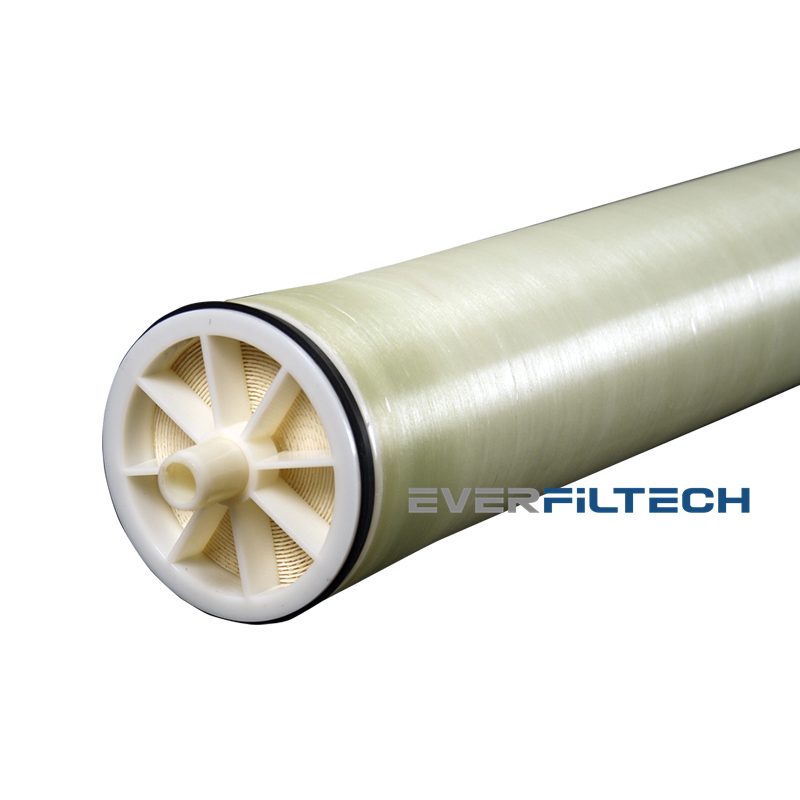
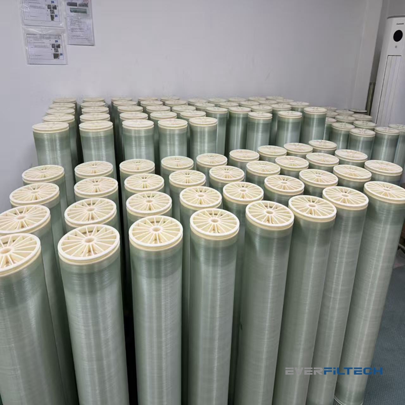
STRO (Spacer Tube Reverse Osmosis) membranes feature a single-element, independent membrane housing design. Each 8-inch (20.3 cm) diameter, 1-meter-long element uses a 27 m² spacer tube. The open flow channel and spiral-wound configuration with turbulence-free feed systems prevent suspended solids (SS) from depositing on the membrane. This design overcomes fouling and scaling issues in traditional RO membranes, making STRO ideal for landfill leachate, electroplating wastewater, and RO concentrate treatment.
The membrane of the STRO module adopts industrial anti-pollution reverse osmosis membranes or nanofiltration membranes, and the grid channels adopt a parallel grid structure different from the common spiral wound membranes, as shown in Figure 2. The coiled membrane module is composed of membrane sheets wound around a central dialysis tube and formed into intervals through a grid. The traditional grid is of a rhombic structure, as shown in Figure 3. When the wastewater/feed liquid flows through this grid, it is not smooth, especially for the wastewater containing certain suspended solids (SS). Therefore, the traditional spiral wound membrane module requires strict pretreatment to prevent SS from entering the interior of the membrane module and causing physical blockage. The grid of the STRO component adopts a trapezoidal structure. The wastewater/material liquid flows in the channels formed by the grid, just like flowing in a tubular membrane, and the resistance is much smaller than that of a rhombic grid. Meanwhile, the internal transverse reinforcing ribs can increase the turbulence during the flow of the feed liquid and reduce the concentration polarization effect of the membrane, thereby enhancing the pollution resistance of the STRO module.
STRO membranes use corrugated RO sheets combined with parallel spacers , rolled around a central permeate tube, and housed in a pressure vessel. Due to its unique design, a corrugated open inlet channel is formed at its inlet port , with the channel spacing reaching 34 to 120 mil (approximately 1.2 to 4 mm), which can reduce flow resistance, lower concentration polarization, and facilitate membrane cleaning. Meanwhile, the pressure resistance capacity of the STR0 component has been improved. The pressure resistance range of ≥ 7.0 MPa can overcome higher osmotic pressure and achieve a high concentration ratio.
STRO’s open channels and independent modules enhance anti-fouling performance. With triple the membrane area of DTRO, STRO is ideal as a secondary stage in landfill leachate DTRO systems, offering higher output, lower pressure, and reduced costs.
- EVERFILTECH®STRO Membrane Product Parameters
The specifications and models of EVERFILTECH® STRO series membrane modules are detailed in the table below:
Table 1: Standard STRO Parameters
| Model | Area (m²) | Spacer (mil) | Feed Flow (L/h) | Permeate Flow (L/h) | Salt Rejection (%) |
| STRO-8040(46)-20 | 27 | 46 | 8000–12000 | 600–900 | 99.20 |
| STRO-8040(80)-20 | 20 | 80 | 10000–12000 | 450–670 | 98.30 |
| STRO-8040(46)-40 | 27 | 46 | 8000–12000 | 400–500 | 99.40 |
| STRO-8040(80)-40 | 20 | 80 | 10000–12000 | 300–380 | 98.50 |
| STRO-8040(46)-70 | 27 | 46 | 8000–12000 | 300–400 | 99.40 |
| STRO-8040(80)-70 | 20 | 80 | 10000–12000 | 220–320 | 98.50 |
| STRO-8040(46)-100 | 27 | 46 | 8000–12000 | 270–380 | 99.40 |
| STRO-8040(80)-100 | 20 | 80 | 10000–12000 | 200–300 | 98.50 |
| Note: For nanofiltration membranes and other models, contact our sales team. | |||||
Table2: STRO PLUS Parameters
| Model | Area (m²) | Spacer (mil) | Feed Flow (L/h) | Permeate Flow (L/h) | Salt Rejection (%) |
| STRO(46)-70 | 27 | 46 | 8000–12000 | 300–400 | 99.20 |
| STRO(46)-100 | 27 | 46 | 8000–12000 | 270–380 | 99.20 |
| STRO(80)-70 | 20 | 80 | 10000–12000 | 220–320 | 98.50 |
| STRO(80)-100 | 20 | 80 | 10000–12000 | 200–300 | 98.50 |
| Note: For nanofiltration membranes and other models, contact our sales team. | |||||
3. EVERFILTECH® STRO Membrane Applications and Case Studies
The open flow channel and single-membrane independent membrane column design of EVERFILTECH® DTRO make the anti-pollution performance of STRO membranes much more ideal than that of traditional reverse osmosis membranes. Therefore, the STRO reverse osmosis membrane system is particularly suitable for the end of zero-discharge membrane concentration, solving the problem that the water at the end of zero-discharge is difficult to be concentrated with ordinary membranes due to high CODcr.
From a cost perspective, the EVERFILTECH® STRO concentration method can reduce the amount of concentrated salt water entering the evaporation crystallization unit, thereby reducing the evaporation volume and the scale of the evaporation unit. Therefore, the application of EVERFILTECH®STRO can save operating costs for zero-emission projects.
Primary Applications:
- Treatment of highly polluted wastewater (landfill leachate, electroplating, pharmaceuticals, chemicals, textiles).
- Wastewater treatment projects for “zero discharge” and “near-zero discharge” in industries such as steel, papermaking, dyeing and printing, and coking.
- The original traditional reverse osmosis treatment system concentrated liquid volume reduction wastewater treatment project.
- Technical Comparison
DTRO vs. STRO vs. SWRO
| Feature | DTRO | STRO | HRRO/SWRO |
| Structure | Disc-type | Special spiral | Conventional spiral |
| Channel (mm) | 2 | 0.8–1.2 | 0.4–0.8 |
| Area (m²) | 9.4 | 27 | 40 |
| Flow Path (mm) | 70 | 1000 | 1400 |
| Spacer Shape | Open | Trapezoidal | Diamond |
| Fouling Resistance | High | Medium | Low |
| Cleaning Cycle | Easy recovery | Easy recovery | Frequent, difficult |
| Pretreatment | Low | Moderate | High |
| Pressure (MPa) | 7.5/9.0/12/16 | 2.0–16.0 | 1.5/4.0 |
| Feed COD | High | Medium | Low |
| Recovery Rate | High | High | Low |
| Maintenance Cost | Low (replaceable) | Moderate | High |
